Brushless motor positive and negative rotation method
Brushless motor forward and reverse
The power supply of the brushless motor is connected to the brushless motor through the controller to make the brushless motor run in one direction. Looking at the motor shaft extension direction the motor shaft is clockwise rotation called positive rotation, counterclockwise rotation called reversal.
In the following two cases, the brushless motor needs to consider the adjustment of the motor steering:
(1) If the brushless motor is found to be positive after rotation, but the actual motor is reversed, then the steering of the motor must be adjusted
(2) if the working state of the brushless motor is to be positive in a certain state and time, and to be reversed in another state and time, then the correct steering of the motor must be controlled according to the working state and time of the motor. During the operation of a general DC motor, changing the direction of the magnetic field or the polarity of the armature voltage can change the motor steering. The magnetic flux of the brushless DC motor is generated by a permanent magnet, which cannot change the direction, and because of the one-way conductivity of the semiconductor, the power supply voltage reverse connection is very inconvenient. Therefore, in this case, the motor rotation direction is generally changed by controlling the commutation order of the stator windings.
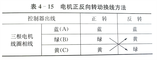
Several methods of brushless motor inversion developed by Changzhou Finer Motor Co., LTD. : First determine the phase line and its color: the Hall component power line is red, negative is black, if the color pair should be positive, then the following situation is reversed, if reversed, the phase line: yellow and green, signal line: blue and green, the motor is also reversed. For details about how to change cables, see Table 4-15.


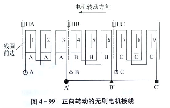
There are several other ways to reverse the motor. The stator of the positive and running motor that has already been launched is shown in Figure 4-99.

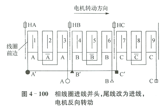
As long as the three entry heads are changed to the tail and connected together, the three tails that are connected together to the head, and after separation as the three phase lines, the motor can be reversed, as shown in Figure 4-100 Essence.

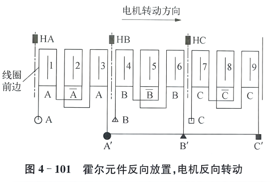
Another method is that the coil winding is completely motionless, reverse the three Hol components, and the motor reverses, as shown in Figure 4-101.

The structure of the above methods is relatively simple. The positioning and placement of Hall component are very convenient for artificial methods to use the coil current of the motor to reverse 180 ° to achieve the purpose of the motor reversal.
In the second case, if the working status of a brushless motor is to be transferred in a certain state and time, and the other state and time are reversed, then the correct steering of the motor must be controlled according to the working status and time of the motor. In fact, the controller is easier to implement the front and reverse of the brushless motor than the modified motor. Because the reversal and positive rotation is just 180 ° between the stator magnetic field, the reversal of the brushless motor is realized. Reverse control is quite convenient.


